Ethernet/IP Allen-Bradley
With the help of the following information you can integrate one or more HERMA 500 IE applicators into a higher-level controller – in this case Allen-Bradley 5380 with Ethernet/IP.
The steps required in the relevant development environment and the initialization (initial configuration) of the underlying parameters in the HERMA 500 IE are described.
You can find all information, sample projects and videos to download here
You can get more detailed information from the above download, incl. FAQs.
Prerequisites
- „Studio 5000 Logix Designer“ by Siemens Rockwell Automation.
- Connection of the HERMA 500 IE to the customer’s controller.
- Optional connection of further applicators HERMA 500 IE
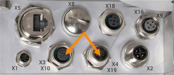
V1 (until end of 2021)
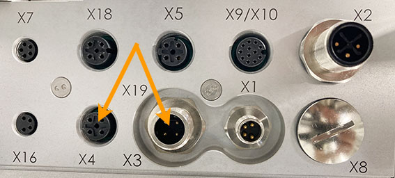
V2 (Facelift) as of 2022
Sample project
To test the successful integration, we provide you with sample projects that let you learn step by step how to switch on the HERMA 500 IE, dispense labels with it and change parameters, for example.
Sample project and associated video tutorial are also included in the download above
You can find a video tutorial here
Integrating the applicator into the PLC
Allen-Bradley-SPS with Studio 5000
The AOI supplied in the sample project, AOI_H500_EIP, controls the data traffic between the PLC and HERMA 500 IE. It must be instantiated once for each connected HERMA 500 IE and called separately by specifying an assigned UDT. A separate UDT is required for each HERMA 500 IE. Each UDT differs only in terms of content.
The program in the AOI is protected against read access. Changes to the UDT are not permitted; otherwise, correct communication cannot be ensured.
Preparations
The following settings must be configured prior to the first connection to the PLC:
- Under “Advanced settings --> Fieldbus settings --> Fieldbus selection (parameter 650),” you must set “Ethernet/IP”.
- You cannot activate the fieldbus communication with the PLC (parameter 651) until parameter 650 is set to “Ethernet/IP”.
To access this parameter, you must be logged in as an administrator.
To apply the data and start in the new mode, you must briefly disconnect the HERMA 500 IE from the power supply (switch the HERMA 500 IE off and on again).
Installing the device file
The HERMA 500 IE is integrated using an EDS file supplied by HERMA. You can register this file in Studio 5000 in the EDS Hardware Installation Tool, which can be found on the “Tools” menu tab.
You can choose “Register an EDS file” to add a device to the database. You then have to select the supplied EDS file. During the registration process, the device is displayed as “EIS_V3_HERMA500”. After the installation is successfully completed, you can integrate a HERMA 500 IE into the project.
Adding a device
IMPORTANT:
In the “Controller Properties”, “A1/A2: Linear/DLR” must be set under Ethernet/IP Mode on the “General” tab. If “Dual-IP” is set here, a connection to the HERMA 500 IE cannot be established.
To add a HERMA 500 IE to the project, right-click “New Module” to add a new module under “Ethernet” in the I/O configuration. The IP address set there must be the same as the IP address set in the HERMA 500 IE. You can find this address in parameter 610 under “Advanced settings -> Ethernet settings”.
The requested packet interval (RPI) can be set to 50% of the processing rate. If communication with the HERMA 500 IE is performed later in a 5 ms task, 2.5 ms is entered here.
The HERMA 500 IE is now displayed as “running” in the I/O configuration if you go online and everything is connected and set correctly.
If the device was added successfully, the inputs/outputs also appear in the controller tags.
Importing the AOI
The add-on instruction (AOI) contains all the programs and data types that are required for communication with the HERMA 500 IE via fieldbus. To import this file, go to “Assets” in the Controller Organizer and right-click “Add-On Instructions”. You must select the file “AOI_H500_EIP.L5X” during the import.
A new window now opens with an overview of the contained components. Choose “OK” to complete the import.
You can then find the required AOIs and the UDTs under “Assets/Add-On Instructions” or “Assets/Data Types”.
Using AOI_H500_EIP in the program
This add-on instruction controls all communication between the PLC and the HERMA 500. After it is installed, it must be created in the controller tags. This can be done only if a module has already been created in the I/O configuration. A new tag is now created here as a communication program of the type “AOI_H500_EIP” – in the sample project, the name of this tag is “H500_Communication_E1” (E1 stands for applicator 1). This AOI must be instantiated once for each applicator in the project. In addition, a separate tag of the type “UDT_H500_DB” is required for each applicator in the project – (“H500_DataBlock_E1” in the sample project). All the parameters and communication variables for the respective applicator are stored within it.
To establish communication with an applicator, the respective AOI must be called cyclically. The possible cycle time depends on the communication usage type and PLC options. During the call, certain parameters must be specified for the AOI:
AOI_H500_EIP(AOI_H500_EIP,iq_DataBlock,iq_Input,iq_Output, i_ConnectionFaulted)
In our example, the call appears as follows:
AOI_H500_EIP(H500_Communication_E1,
H500_DataBlock_E1,
H500_E1:I.Data,
H500_E1:O.Data,
H500_E1:I.ConnectionFaulted);
Another summary of the individual parameters:
|
Type |
Variable |
Description |
|
AOI_H500_EIP |
H500_Communication_E1 |
Instance of the AOI assigned to the applicator. |
|
iq_DataBlock |
H500_DataBlock_E1 |
Instance of the UDT_H500_DB assigned to the applicator. |
|
iq_Inpu |
H500_E1:I.Data |
Array of 8 bytes – communication from the applicator to the PLC. |
|
iq_Output |
H500_E1:O.Data |
Array of 8 bytes – communication from the PLC to the applicator. |
|
i_ConnectionFaulted |
H500_E1:I.ConnectionFaulted |
Applicator communication error bit.-Bit des Etikettierers |