Profinet Schneider
With the help of the following information you can integrate one or more HERMA 500 IE applicators into a higher-level controller – in this case Schneider Electric PacDrive LMC101C.
The steps required in the relevant development environment and the initialization (initial configuration) of the underlying parameters in the HERMA 500 IE are described.
You can find all information and sample projects to download here
You can get more detailed information from the above download, incl. FAQs.
Prerequisites
- “Logic Builder” by Schneider.
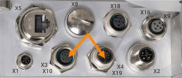
- Connection of the HERMA 500 IE to the customer’s controller.
- Optional connection of further applicators HERMA 500 IE:
V1 (until end of 2021)
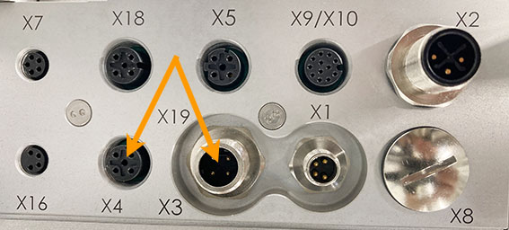
V2 (Facelift) as of 2022
Sample project
To test the successful integration, we provide you with sample projects that let you learn step by step how to switch on the HERMA 500 IE, dispense labels with it and change parameters, for example.
This project is included in the download offered above, as well as explanations supplemented with various screenshots, examples, exercises and a video tutorial.
Integrating the applicator into the PLC
Schneider Electric PLC with Logic Builder
The library supplied in the sample project controls the data traffic between the PLC and HERMA 500 IE. It must be instantiated once for each connected HERMA 500 IE and called separately under “Main POU” in the program. Each instance of the library also contains a data block for the respective HERMA 500 IE. The library is compatible for use with Logic Builder V4.41 or higher and Machine Expert V2.1 or higher.
The library is write-protected and cannot be changed.
Preparations
The following settings must me configured prior to the first connection to the PLC:
- Under “Advanced settings --> Fieldbus settings --> Fieldbus selection (parameter 650)”, you must set “Profinet”.
- You cannot activate the fieldbus communication with the PLC (parameter 651) until parameter 650 is set to “Profinet”.
To access this parameter, you must be logged in as an administrator.
To apply the data and start in the new mode, you must briefly disconnect the HERMA 500 IE from the power supply (switch the HERMA 500 IE off and on again).
Adding functions and data blocks to your project
The sample project provided by HERMA is intended for an application with three HERMA 500 IE devices. If you are only using one HERMA 500 IE, you only have to copy the functions, data blocks and variables for “E1” (applicator 1). Repeat the steps for E2, E3 to En, if you are using more than one HERMA 500 IE applicator in your device.
- Open your actual project in the Logic Builder.
- Open a second instance of the Logic Builder and open the sample project provided by HERMA.
- Copy all the relevant global variables from the sample project to your project. The sample project contains the global variables for three HERMA 500 IE devices. Adapt the number of variables to the number of HERMA 500 IE devices in your project.
- Copy the required functions and add them to your project. The HERMA500_DB_EN (FUN) is a comment only reference file for easy access to an overview of the data block structure and commentaries.
- Open “Main” and copy the variable definition and the source code to your project. This is where you create instances of the data block (all the parameters) and the function responsible for the communication, data exchange and the processing of the parameters and the exchanged data between HERMA 500 IE and the PLC.
- Open the library manager in your project and open the library repository. Install the library from the sample project folder. Following the installation, add the library to your project. The library contains the communication function and the data block with the parameters that you instantiated in the previous step.
You can find a more detailed description of the content below.
You can find an overview of the data block below. Following these steps, you can continue with the hardware configuration for the fieldbus.
PacDrive LMC101C Logic Builder sample setup for configuration
Firstly, you import the current GSD file for the network controller fieldbus into the project (the GSD file is located in the sample project folder). To install the GSD file, go to the main menu in the project view and choose “Tools --> Device Repository --> Install”. Based on the number of HERMA 500 IE devices integrated in the project, the same number of fieldbus controllers should be added to the project. To do so, proceed as follows: Devices view --> right-click the controller --> Add device --> Profinet IO --> Profinet IO Master --> Profinet IO Controller.
You now add the HERMA 500 IE to the hardware configuration by right-clicking the Profinet controller that you just added then “Add device”. Now go to “Profinet IO Slave” and select the latest version of the model (e.g. NETX 52 RE/PNS v4.4.0x). The NETX controller for the HERMA 500 IE should now be displayed. Repeat the steps for E2, E3 to En, if you are using more than one HERMA 500 IE applicator in your project.
You must now parameterize the IP address, inputs and outputs and name of the fieldbus controller. The IP addresses must be in the same range as those of the PLC. The device overview opens automatically when you double-click the PNC controller or NETX controller.
For I/O mapping, use the global variables defined earlier.
8 bytes in the input range
8 bytes in the output range
If you are using more than one HERMA 500 IE device, repeat this step accordingly. For the communication to work you must assign HERMA 500 IE with the same name and IP address as the one in the hardware configuration in your project. To do so connect HERMA 500 IE to the PLC then right click the PNC-Controller and click on Scan for Devices. A new window will pop up where you can set name and IP-Address to the HERMA 500 IE device.
Then connect the HERMA 500 to the PLC. Translate the project and download it to the CPU. You can now go online and test the availability of the participants. Once you have successfully completed the hardware configuration, the Profinet connection should function.
If everything is configured correctly the first five bits of the communication status structure will be TRUE, meaning the HERMA 500 IE and the PLC are successfully communicating.